
The circuitry of the Gibson Victory bass was the work of Gibson R&D team member Tim Shaw. Electrical components on the Gibson Victory Artist are accessible by removing the pickguard. See also the Victory Artist wiring photos.
There were two versions of the Gibson Victory Artist circuit. The first was used perhaps only in early-mid 1981. This is characterised by having the active/passive switch mounted on the scratchplate. The second is far more common and was labelled Revision B or Rev B on the circuit board itself. It has this switch soldered to the board, and three extra capacitors, affecting biasing within the circuit. The end result is a slight reduction in the high end bite when the treble is full on.
The Schematics are shown below. Click to enlarge (enlarged copy is in pdf format, for easy printing). Thanks to Kirkwood Rough for the creation of these schematics.
The first version of the Gibson Victory circuit (that we shall name Rev A)
The second version of the Gibson Victory circuit, Rev B
Gibson Victory bass switch layout, common to both Rev A and Rev B
Gibson Victory bass for sale
Gibson Victory Artist Bass 81'
Blackfoot, Idaho, 832**, UNITED STATES OF AMERICA
$3800

Vintage 1981 Gibson VICTORY STANDARD BASS with Original Case Candy Apple Red
Miami, Florida, 331**, UNITED STATES OF AMERICA
$1295

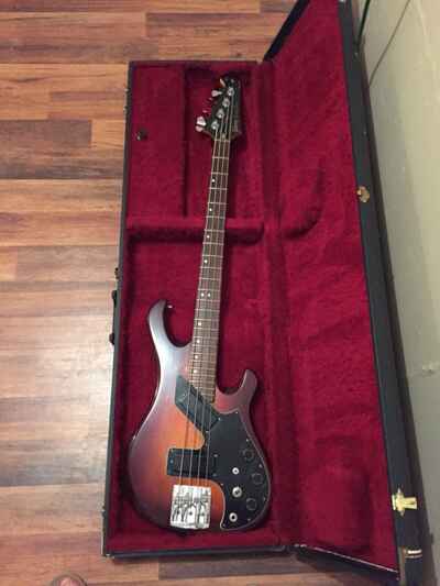
Vintage Gibson Victory Artist Bass Sunburst 1981
Brookfield, Wisconsin, UNITED STATES OF AMERICA
$1999
Vintage Gibson Victory Artist Bass Sunburst 1981
PLEASE CONTACT US WITH ANY QUESTIONS OR FOR AN IN-HAND DESCRIPTION
Made for only a brief moment in the early to mid '80s, the Victory Artist bass features dual humbuckers with active electronics all wrapped up in a classic sunburst finish. Professionally set up & ready to play straight out of the case
Cosmetic Condition: Really nice shape for being over 40 years old with signs of some typical play wear - various little nicks, ... more

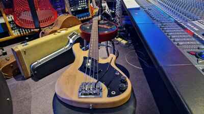
GIBSON VICTORY STANDARD BASS GUITAR
Saint Petersburg, Florida, 337**, UNITED STATES OF AMERICA
$1750
... more

Vintage 1981 Gibson Victory Standard Bass Guitar ~ Candy Apple Red ~ Nashville
Santa Ana, California, 927**, UNITED STATES OF AMERICA
$1300
Model: 1981 Gibson Victory Standard bassPickups: One Series VIIB humbucker Scale: 34 " Body: Eastern hard-rock maple. 19 1 / 2" long, 13" wide, 1 3 / 4" thick. Overall length 47 " Neck: 24 fret, two-octave maple bolt-on neck. Rosewood fingerboard. Width at nut 1 6875 " Hardware: Chrome throughout: TRI-4 wedge bridge, Gotah machine heads
Pleasetake advantage of the zoom feature on the photos to judge ... more
Gibson Victory Bass 1981 Vintage USA Kahler Tremolo Thunderbird Headstock
Southend-on-Sea, SS1***, UNITED KINGDOM
£1999

VINTAGE 1982 USA GIBSON VICTORY BASS GUITAR TUNER
Monza, 20***, ITALY
€50
Gibson used these on the Victory Standard and Victory Artist basses from 1981, and occasionally the Victory Custom later in 1982
Hard to find, very rare and no longer produced
Very good condition, see pictures
Price for one tuner, available 4 tuners
Private auction, non guarantee
European bidders please email me for postage costs
... more